As shown in Figure 5, through the chemical conversion of non-recyclable municipal and industrial waste, mainly plastic and dry waste, the resulting hydrogen and carbon oxides (syngas) can be used to produce more sustainable methanol. The core of the process is the gasifier, where feedstock (RDF/SRF/dried sewage sludge/wood) from battery limits is mixed with oxygen to produce a syngas whose major components are hydrogen, carbon monoxide, carbon dioxide, and methane. Such a stream also contains salts and particulates, HCl, COS and H2S, and HCN. All these components need to be removed before any further catalytic treatment takes place.
The high temperature and the appropriate temperature profile are the key parameters to achieving proper performance of the gasifier. In particular, hydrogen content increases and tar content remarkably decreases at temperatures higher than 1000 °C, methane and other hydrocarbons tend to decompose at temperatures above 600 °C, and a small amount of char is present at temperatures as high as 1600 °C and is discharged into the slag. Moreover, the absence of an oxidizing atmosphere eliminates one of the steps of the dioxins synthesis mechanisms and strongly reduces their formation to an undetectable level.
The gas leaves the converter at around 1100 °C and is quenched with water to reach near ambient temperature to enter into a first absorption tower containing water and then into a second tower containing an alkaline solution to remove particulates, salts, and HCl. A wet electrostatic separator will act as a final cleaning unit. The raw syngas coming from several different lines is routed to an atmospheric tank.
From the storage unit, the gas is compressed, COS is hydrolysed to H2S, which in turn is removed by a redox sulphur removal unit, followed by an H2S deep polisher. The processed gas is split into two streams, one going directly to the methanol synthesis, the other routed to the shift reactor(s) in order to convert CO into H2 and CO2, which is then removed throughout the cryogenic unit. The excess CO2 provides a CCS deployment option with little additional cost and represents one of the key “low-hanging fruits” for Bio-CCS. Raw hydrogen is added to the previous stream in order to get the proper CO/H2 ratio before routing the streams to the methanol synthesis reactor. The purge gas will be recycled to the gasifier to support the RDF conversion.
Together with chlorides, which are removed downstream of the RDF conversion step, sulphur is a particularly severe poison for the catalyst of the WGS and the methanol synthesis reactors. A proper desulphurisation system is required in order to reduce sulphur compounds to less than 0.1 ppm or even lower. The limit for chloride contamination is below 5 ppb. Sulphur is present in RDF-generated syngas mainly as hydrogen sulphide (H2S) and carbonyl sulphide (COS), although minor amounts of carbon disulphide and other sulphur compounds are also present. The H2S/COS ratio is typically around 10 to 1. COS is thermally stable, and it may not be hydrogenated completely over a cobalt molybdate catalyst. Moreover, direct hydrogenation of other sulphur compounds over a nickel or cobalt molybdate catalyst in the presence of CO and H2 may become problematic because of the possibility of methanation as a side reaction. In addition, the presence of significant amounts of H2S does not allow the use of zinc oxide absorbents because of the high cost. The scheme indicated in below figure presents removing sulphur components based on the following steps: COS hydrolysis, H2S removal throughout a redox system such as the Lo-Cat, followed by a guard bed to remove all traces of sulphur contaminants.

Figure 10: Block diagram for the removal of sulphur compounds
Watch this video:
Enerkem, a waste to methanol process technology which is using fluidised bed gasifier.
Watch this video:
NextChem, a subsidiary of Maire Tecnimont S.p.A with Johnson Matthey support uses a WtM process technology which utilises a fluidised bed gasifier.
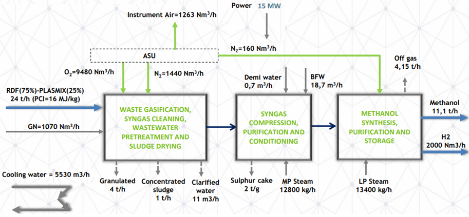
Figure 11 presents the mail parameters of an actual waste to methanol plant.

Figure 11: Schematic flow diagram for a waste to methanol process
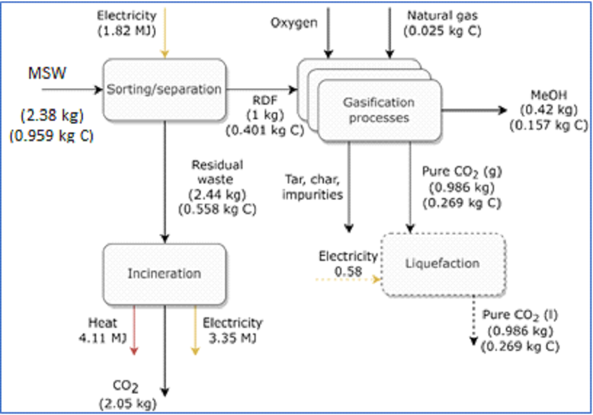
A methanol plant with 716 tonnes/d of RDF feedstock produces 300 tonnes/d of methanol based on the mass balance shown in Figure 12. This process requires a further 0.08 MJ per kg RDF for the air separation unit to supply the oxygen for the system. Dotted lines indicate possibility of CO2 storage. This process has a 39% carbon efficiency from RDF to methanol. If MSW is included, the carbon efficiency is 16%.
AdWinMethanol® technology is the advancement of the existing methanol technologies, which brings some considerable improvements and advantages for the owner/operator:
- Improved reliability
- Reduced EPC cost for a 5,000+ mtpd AdWinMethanol® plant
- Reduced natural gas consumption
- Significantly reduced catalyst cost
- More simple operation

Figure 12: Mass balance around a typical waste to methanol plant
As per gasification of MSW, water-gas shift reaction and methanol formation reaction (shown below), waste to methanol technologies produce less CO2 than WtE and WtH technologies.
CO + H2O —> CO2 + H2
CO + 2H2 —> CH3OH
_____________________________________________________________________________________________
3CO + 2H2O —> 2CO2 + CH3OH or CO + 0.667H2O —> 0.667CO2 + 0.333CH3OH