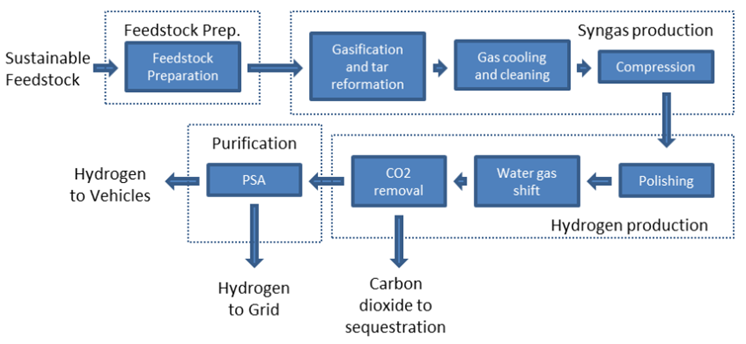
The process is made up of the following steps:
- Feedstock are RDF, SRF, wood, dried sewage sludge which are made up of waste and biomass residues such as household waste, waste wood, straw, sawdust or sugarcane bagasse. They are prepared for the process through shredding, sorting and drying as discussed in the section 3 and conveyed to gasifier.
- The feedstock in the presence of limited amounts of oxygen is heated within the gasifier and generates a crude synthesis gas which is made up of hydrogen, carbon monoxide, carbon dioxide, tars and ash. The tars and ash must be removed for the syngas to be processed further. This is achieved through some combination of further heating, wet scrubbing and catalytic conversion. The clean syngas is compressed and polished before being converted into a usable product.
- The carbon monoxide in the syngas reacts with water (steam) to produce carbon dioxide and hydrogen in a process known as the water gas shift. Conventionally this is carried out over an iron oxide-chromium catalyst (high temperature shift) or copper-based (low temperature shift) catalyst under carefully controlled conditions to optimise the amount of hydrogen produced. In Sorption Enhanced Water-Gas Shift (SEWGS), the CO2 is removed as it is produced to drive the reaction to produce large amounts of hydrogen.
- The output from the water-gas shift is a mixture of CO2 and hydrogen. The CO2 is captured by chemicals (MEA, hot potassium carbonate) or MOFs, compressed and dried to be utilised and stored safely, thus ensuring it doesn’t return to the atmosphere.
- The hydrogen that is leaving the carbon dioxide capture system will normally contain significant levels of contaminants such as carbon monoxide or methane. The gas is cleaned using a Pressure Swing Adsorption (PSA) process. The output from this process is a high quality biohydrogen stream.
Watch the video:
Powerhouse Energy Group PLC, is one of the world’s first proven, distributed, modular, WtH process. The Powerhouse process can 1 tonne of road-fuel quality hydrogen or 58 MWh of exportable electricity per day from 25 tonnes of plastic.
RWE is investing on a process where torrefaction, entrained flow gasifier and Air Liquid WGS and Rectisol technologies are utilised to produce hydrogen from SRF and dried sewage sludge.
As per gasification of MSW and water-gas shift reaction of CO (shown below), WtH technologies similar to WtE technologies produce the maximum CO2 compared to the other WtV technologies.
C + 0.5 O2 —> CO
CO + H2O —> CO2 + H2
CO2 can be captured at high pressures within WtH technologies; therefore, CCUS cost of the WtH technologies is lower than WtE technologies and is higher than other WtV technologies.
There are two demonstrated types of WtH technology, namely Fluidised Bed (FB) and Entrained Flow (EF).
1. WtH-FB
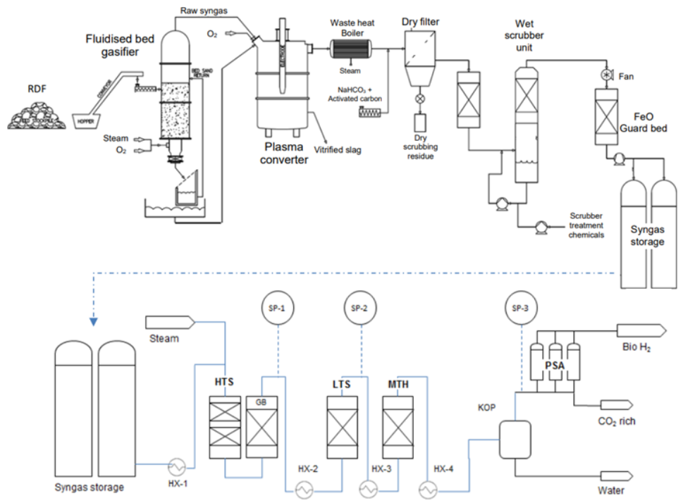
In the FB technology, fluidised bed gasifier operates at atmospheric pressures and generated crude syngas is then heated and exposed to oxygen free radicals within a plasma furnace to catalyse the reformation of tar.
The tar free syngas is cooled in a waste heat boiler with boiler feed water and the produced steam is taken to be used elsewhere in the process. The gas is filtered to remove particulates and scrubbed to remove acid and alkali contaminants. At this point cool, clean, chemical grade syngas is available.
The process is summarised in Figure 8.


Figure 8: WtH-FB schematic flow diagram
2. WtH-EF
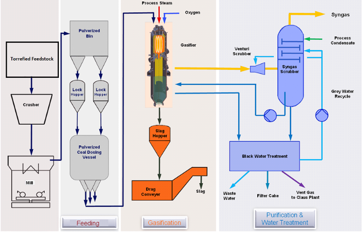
In the EF technology, entrained flow gasifier operates at high pressures (up to 40-50 barg) and generated crude syngas with minimum tar content due to its higher operating temperature compared to fluidised bed gasifier. The tar free syngas is cooled and saturated with water in a direct cooling scrubber coupled with the gasifier and a black water treatment system. To operate the entrained flow gasifiers, it is required to have a fairly uniform feedstock, namely torrefied and milled feedstock. Figure 9 present schematic flow diagram of the gasification process for a WtH-EF technology.

Figure 9: WtH-EF gasification schematic flow diagram